Architectural Design:
3D is applied to a lot of different subjects such as games, product design, TV, film, education, architectural designs, animations etc. When it comes to applying 3D into these different subjects, they are all used in very different ways. A lot of architectural designs rely on 3D models and animations. The reason behind this is so that a person is able to view what this future build will look like from every angle. Furthermore, the 3D model really covers the scale of objects. It also allows the people that are viewing this architectural idea a good idea of what it would look like in reality.
This video clip is a great example showing what a 3D architectural animation looks like. The colours and the different perspectives it offers really gives the viewer a taste of what it will look like in reality. The scale of the people compared to building also adds a great effect to how big this build will be. If this was a 2D animation of how the build will look like, we wouldn't be able to see the true scale of the objects and buildings, furthermore, we would not be able to look from other perspectives in case something needs to be changed, into a better design. This video did not only cover the overall designs of buildings, but it also included animated people and considered how the environment would look to. The animation really livens up the whole video and adds a great overall environment.
Product Design:
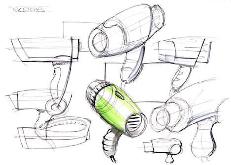 Product design also uses 3D software to create models which allows the user to get a good feel of how the product will look when it is it finished. It all comes back to the scale of the product, the colours, the size, the size of the components and so on. Drawing 3D sketches is one point of gathering a good idea on how it will look like from different angles, however it would cover all the angles as much as a 3D model would. Furthermore, a 3D model can give you accuracy moreover than a 3D sketch of a design for a product.
This video clip is a someone's portfolio of products that they have created, designed and rendered in. They have included different perspectives of what the products would look like, the size comparison of the components, colours, lighting and so on. This portfolio is a great example of a bunch of different products which have been 3D modelled.
Games:
Games are heavily reliant on 3D models. 3D models are now used for most games whether they are cell-shaded type games or photo-realistic styled games. What game developers create with 3D modelling software are the characters which are contained within the games, objects, weapons and environmental objects. The models are essential to how the game plays and looks overall. The character models are needing to follow the sort of styled game you are going for. Whilst using the 3D software for creating models for a game, they can also create the animation for those models with the software. For example, Maya.
This video clip displays a man creating a video game character which is going to be a part of a real-time game. This is a video which has got the speed increased to show how he has used a 3D modelling software to create the desired character that he has wanted to sculpt. The program allows him to rotate his character to be able to see the model form all perspectives. This helps him see if all of the proportions are right and correct.
Animation/Films/Tv:
3D animations require 3D models which are then rigged using a 3D software program. 3D animation really draws in the viewer due to the colours, models and lighting. 3D animations have now replaced the old style of how animations were made. The way animations were made before 3D software, it was drawing the animation frame by frame. Now with animation, you can use rigging on your 3D models. Rigging is essentially the skeleton of that object. A skeleton has joints and bones, animators are able to adjust and change the pose at which they want the model to stand as/sit as and so on.
When it comes to films and Tv, they use 3D software differently. Game of Thrones is a good example as they use 3D software to create visual effects within the episodes. Green screen is often used to also create 3D backgrounds for the scenes within films and TV episodes.
This is a great example of showing how animation were done before animators could use 3D modelling programs. Throughout the video, it shows us how they would first create a frame and then how they would add colour to that frame and then add into a scene.
Both videos shows a great contrast between how animation is made now and how animation was done back then.
This video clip is a short animated 3D film.This is a great example of a result from making a 3D animation short film by using 3D modelling software.
This relates back to the example of TV shows using 3D modelling software and green screen to create 3D visual effects within episodes of a TV series.
Time spots:
5.16-6.00
Displaying 3D Polygon Animations:
API which is Application Program Interface interacts with GUI components. An example of an API is Direct3D. Direct 3D graphics are used to create 3D graphics for games and other uses. It is an API which works with the Windows OS and is a low-level graphics API in which can also take advantage of hardware acceleration such as graphic cards. It is used to render 3D objects without sacrificing performance. OpenGL stands for Open Graphics Library and is another API which was originally developed by Silicon Graphics in 1991. It is said that the OpenGL is widely used, it supports 2D and 3D graphics and can be used on a variety of computer platforms. The high visual quality and performance helps produce and display brilliantly compelling graphics, whether 2D or 3D. SceneKit is another API which is specific to an OS. SceneKit is an API which is specifically for Apple. What makes this different form OpenGL is that, with SceneKit you do not need to input deatil into the rendering algorithms it has, you only need to do a descriptions of the scene's content and then describe the animations/actions you want the SceneKit to perform.
Graphics Pipeline:

Modelling
The graphics pipeline for Direct3D 11 is "designed for generating graphics for realtime gaming applications". The diagram to the left displays the orders of stages on how the pipeline works. Altogether there are 10 stages that it goes through; Input-Assembler Stage, Vertex Shader Stage, Hull Shader Stage, Tessellator Stage, Domain Shader Stage, Geometry Shader Stage, Stream Output Stage, Rasterizer Stage, Pixel-Shader Stage and Output-Merger Stage. The Input-Assembler gives data to the piepline such as triangle, lines and points. Then the vertex-shader stage processes the vertices and takes a single input vertex and produces a single output vertex. It carries out procedures that are to do with transformations, lighting and skinning. The geometry-shader can get rid of/create one or more primitives. What I mean by the term primitives are; 1 vertex for a point, 2 vertices for a line and 3 vertices for a triangle. Furthermore, it supports limited geometry amplification and de-amplification.
The stream-output stage connects with the memory and the rasterizer. It streams the primitives from the geometry shader and delivers to the memory which is on it's way to the rasterizer. When the data is streamed out of the pipeline and into the memory, it can go back around and back into the pipeline as input data/read-back from the CPU. The rasterizer stage prepares the primitives which were streamed from the stream output for the next stage, clips them and then determines how to call forth pixel shaders. The pixel-shader stage generates per-pixel data (colour) for the primitives. The last stage is the output-merger which then combines the many different types of output data to generate the final result. The three stages in which I missed out were the hull-shader, tessellator and domain-shader stages. These 3 shaders are all tessellation stages. They basically convert high order surfaces to triangles.
https://msdn.microsoft.com/en-us/library/windows/desktop/ff476882%28v=vs.85%29.aspx?f=255&MSPPError=-2147217396
Rendering techniques:
When it comes to rendering, it means changing a model into an image, however because this image is a model (3D) , it would include textures, shading, lighting, viewpoint etc. Parallel rendering uses parallel computing which is many calculations that are all carried out/executed at once. The reason behind why parallel computing is used is due to the complex scenes which can be created that are scientifically visual. For example; Radiosity.
Radiosity is a method of detailed analysis of light reflections. This is one of the complex visuals that are included within parallel rendering. There is an equation in which radiosity uses; Idiff = IePd(Ue+Un). Un is Normalised Surface normal, Ue is Normalised Vector Pointing from surface to light source, Pd is Diffuse reflectivity of surface, Ie is intensity of light source and Idiff is Diffuse light intensity.

As you can see above, the radiosity has added a softened light effect into the room and has also add a realistic light effect to the scene. Furthermore, it has created shadows within the room which are subtle and soft. Ray tracing is a technique which generates an image by tracing the light generated on 3D graphics. What it tries to do is simulate a path of light rays which bounce around the world, then they are traced through the scene.

Rendering Engines:
There are various amounts of rendering engines which are available. A rendering engine is software in which reads pixel data from a file system and then draws text and images on the screen (map the pixel data).
I have found a website in which tests and compares a few rendering engines. How they test them is they create a scene within blender and then they render the scene. The numbers in the bottom right are actually how long it took for them to render. The lower the render time the better the rendering engine was. For this scene in particular, you can notice differences within the scene. For example, if you look are all of the green end tables, some are textured, some are quite plain, and they are all different shades of green. This scene also tests how the indirect light would work within the scene.


This comparison is a great example to show there are different types of rendering engines which work all different and it shows the capability on how they can handle certain scenes.
https://www.blenderguru.com/articles/render-engine-comparison-cycles-vs-giants/
Geometry Theory/Mesh Construction:
When it comes to 3D modelling, you first start off with a choice of different shapes in which you can use. However, how these shapes become models is a different matter. With the polygons, you are able to adjust and change the shape by editing where the vertices are place, which angle the edge is tilting, adjust the size of a face on the shape and so on. A mesh is a collection of; vertices, faces and edges. In Maya, you can switch between what mode you view your model in, there is a wire frame mode, shaded mode, shaded with hardware-rendered texture, wire frame on shaded, default material etc. Furthermore, there are different model types; Polygons, NURBS and Subdivison Surfaces. Polygons allows the user to model a surface by building it up and reshaping it and so on. NURBS lets you easily create curves using its tool, these curves can then be created in models. Subdivision surfaces allows the user to edit surfaces with minimum overhead data. Here is a preview of a few polygon primitives. These are also a few of the common primitives which are used within 3D modelling software.The image below displays the primitives in their shaded mode.

Below is an image of three polygon primitives in wire frame mode. The wire frame mode allows you to keep easy track on your models within the panels view. Furthermore, you can change the colour of the wire frame for each model, so it is even more easier to keep track on where all of your models are.


This is an example of a model that was created using NURBS. To create this they used a CV curve tool (Control Vertices). NURBS are Non-Uniform Rational B-splines. NURBS are most commomly used by designers who model for industrial/automotive designs. The reason behind why they use this is due to the smooth forms that they can create. They can also be converted into a poly mesh.

These example are from the software Maya. These two images on the left are an example of using the extrude tool. The first image on the left is; i selected the far right face of the polygon and then selected to use the extrude tool. Then by pulling the yellow arrow (was blue before, but when you click on an arrow it highlights it yellow) you are extruding that face outwards the right. You are able to extrude any face in any direction. However, if you extrude a face and push it inwards it will then extrude into the box. You can model a box in various different ways. If you press F9 you will be in vertex selection mode.If you click on a vertex, you are able to move it around by using the arrow keys. Another mode is edge selection mode (F10). With this, you are able to select what edges you would like to move around, resize, delete etc. When you hover your mouse over the edges of your model, they will be highlighted red.
 F11 is the mode for selecting faces, which is the mode I used for selecting the highlighted orange face in the images to use the extrude tool on. The last mode which is quite significant is the object mode (F8). This allows you to move the model around as a whole, rotate it and resize it. When you are in object mode, the model will be highlighted green, when you are in the other modes, your model will be highlighted in blue.
The image at the bottom is a reference to box modelling. The shape below was a cube however, I have used the vertex selection tool to model the primitive into what I desired.

3D Development Software:
There are many different 3D development software in which is available for designers. Considering there is a variety of 3D modelling programs, it allows the designers to choose the correct software for them and their purpose. The different 3D modelling programs also vary in which tools they have and what they cover.
3D Studio Max;
3D Studio Max 2016 software is supported on 64 bit OS's such as; Windows 7, 8 and 8.1 whereas 3D Studio Max 2017 is supported on; Windows 7, 8, 8.1 and Windows 10. It requires 64-bit intel or AMD multi-core processor, 4GB of RAM minimum although 8GB is recommended, 6GB of free disk space for the install, and a 3 button mouse (left, right and middle button). 3D studio max is a software program which designers use to model, animate and render scenes. It supports DirectX11 shaders and has tools for particle animation, crown generation and perspective matching. This is commonly used for games, films and motion graphics. Below is an image of the 3D studio max HUD.

Maya:
Maya is another 3D modelling software which allows for designers to model, animate and render in scenes. Maya is a 3D modelling program that I use so I know what is on the HUD and how to access the different areas of Maya in which will suit my needs. Maya has next-gen display technology and has tools in which can handle complex data. Maya software requirements are windows 7,8,8.1 and 10, Mac OS X, Red Hat Enterprise Linux and CentOS 6.5 Linux OS, 64-bit Intel/AMD multi-core, 4GB of RAM (8GB recommended), 4GB of free disk space and 3 button mouse.

Lightwave:
Lightwave is another 3D modelling program which is supported on Windows and Mac. For windows machines, Intel/AMD Athlon 2 Processor or better, 64-bit system RAM 4GB, 32-bit system 2GB minimum, 64-bit Windows vista up to Windows 10 and 32-bit Windows Vista up to Windows 10. For MAC OS, Intel Processor, 64-bit system RAM 4GB minimum and Snow Leopard 10.6 or better. A few of the feature that they have are; Bullet (Constraints and Motors), Importance Sampling (Better, cleaner renders), Match Perspective (Plate matching in minutes), Genoma 2 (Fast, flexible rigging), Edge Rendering (Improvements), Interactive Dynamic Parenting (Parent with ease) and Enhancements (Feature Improvement).

Constraints:
There are constraints however to developing in 3D software. One of those is the poly count (Polygon Count). If there is a high poly count, the game may just freeze over and not work due to how much needs to be rendered in. On the other hand, if the poly count is low then it will be able to run a lot smoother. There are also limitations which are in place. For example, when it comes to the app store, their limitation is the maximum size of the app which you are allowed to send to be reviewed and placed within the store. The maximum size of the app before February, 2015 was 2GB, after that time period it is now 4GB. Another constraint is the rendering time. If you create a scene with a high poly count, high quality textures, lighting, shadows etc, the rendering time will be quite large. This could possibly be cut down by a small amount dependent on the rendering engine you use.
https://techcrunch.com/2015/02/12/ios-app-size-limit/